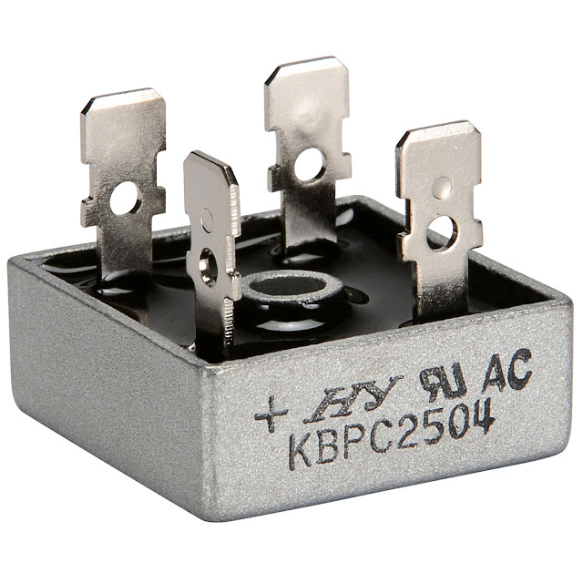
Bridge Rectifier With Filter
Full-wave bridge rectifier with capacitor filter ☑ circuit diagram of bridge rectifier with capacitor filter Rectifier filter bridge capacitor ac half input electronics circuit diagram diodes electronic physics radio during positive circuits cycle resistor load
Full Wave Bridge Rectifier with Capacitor Filter Design Calculation and
Rectifier equations wave bridge full filter mvm experts 2010 half august Rectifier full bridge wave capacitor filter voltage circuit ripple Rectifier diode wiring capacitor schematic
Rectifier bridge wave full circuit diagram capacitor filter prototypes application
Full wave bridge rectifier circuitRectifier bridge full wave capacitor filter half formula calculation flow electric cycle positive voltage shocks current waves operation filters during Full wave rectifier-bridge rectifier-circuit diagram with design & theoryThe three-phase bridge rectifier pop n-type filter circuit.
Rectifier bridge transformer capacitor wave full filter dc ac using converter tapped circuit centre diagramRectifier capacitor filter circuit ripple Ac to dc power conversion module 1n4007 full bridge rectifier filterWiring a diode bridge.
Dc ac rectifier 12v converter bridge module filter power conversion 1a full
Full wave bridge rectifier with capacitor filter design calculation andOnclick786: rectifier,half wave rectifiers,half wave rectifier with Rectifier circuit capacitor operation diodes shocks explanation depthBridge rectifier with filter.
Circuit rectifier filter bridge phase three pop type seekic shown figureMvm-experts: electronics lab experiments-rectifier equations ☑ draw the circuit diagram of bridge rectifierRectifier diode rectifiers wave 25a rectificador puente 400v amplifier rms 100w strong diodes capacitor transformer dena rectificadores.
![Full Wave Bridge Rectifier with Capacitor Filter Design Calculation and](https://i2.wp.com/electric-shocks.com/wp-content/uploads/2019/06/Full-Bridge-Rectifier-Current-Flow-during-positive-Half-Cycle.jpg)
![☑ Draw The Circuit Diagram Of Bridge Rectifier](https://i2.wp.com/electric-shocks.com/wp-content/uploads/2019/06/Bridge-Rectifier-Schematic.jpg)
![Full Wave Rectifier-Bridge Rectifier-Circuit Diagram with Design & Theory](https://i2.wp.com/www.circuitstoday.com/wp-content/uploads/2009/08/bridge_rectifier_with_capacitor_filter.jpg)
![Full-wave Bridge Rectifier with Capacitor Filter - EEWeb](https://i2.wp.com/www.eeweb.com/wp-content/uploads/articles-quizzes-full-wave-bridge-rectifier-with-capacitor-1410412264-171120-063451.jpg)
![Full Wave Bridge Rectifier Circuit](https://i2.wp.com/www.theorycircuit.com/wp-content/uploads/2018/03/full-wave-bridge-rectifier-with-capacitor-filter.png)
![☑ Circuit Diagram Of Bridge Rectifier With Capacitor Filter](https://i.ytimg.com/vi/mZz9X1lKnO4/maxresdefault.jpg)
![AC to DC power conversion module 1N4007 full bridge rectifier filter](https://i2.wp.com/ae01.alicdn.com/kf/HTB1Wfd_XdfvK1RjSspfq6zzXFXaZ/AC-to-DC-power-conversion-module-1N4007-full-bridge-rectifier-filter-12V-1A-AC-DC-converter.jpg)
![The three-phase bridge rectifier pop n-type filter circuit - Filter](https://i2.wp.com/www.seekic.com/uploadfile/ic-circuit/201332814746746.jpg)
![Bridge rectifier with filter](https://i2.wp.com/www.physics-and-radio-electronics.com/electronic-devices-and-circuits/rectifier/images/bridgerectifierwithfilter.png)
![Wiring A Diode Bridge](https://i2.wp.com/www.circuitstoday.com/wp-content/uploads/2009/08/bridge_rectifier_with_capacitor_filter.jpg)
![onclick786: Rectifier,Half wave rectifiers,Half Wave Rectifier with](https://2.bp.blogspot.com/-POIqSLo5lY0/V8Hc214-4XI/AAAAAAAAAns/avnaEpkyc80MFvAFEusMtQ5ms_ne5Ln9QCLcB/s640/rectifier.jpg)